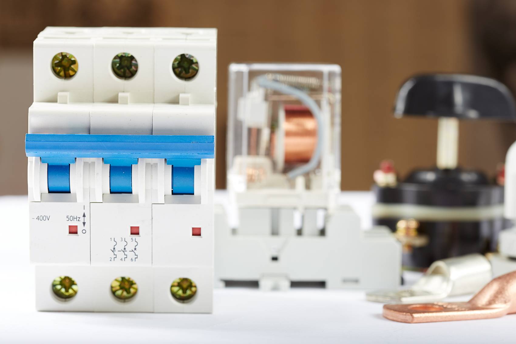
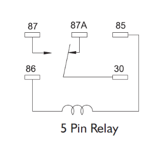
5 pin relay wiring diagram
2024-08-28
Composed of 5-pin relays
A 5-pin relay is mainly composed of three core components: coil, contacts, and housing. A coil is a component that generates a magnetic field. When powered, it produces enough magnetic force to drive the movement of the contacts. The contacts are responsible for the on/off control of the circuit, and affect the working state of the controlled circuit through their opening and closing states. The shell plays a role in protecting internal components and isolating external interference.
working principle
When a certain current is applied to the coil of a 5-pin relay, a magnetic field is generated inside the coil. This magnetic field will attract the armature (also known as the moving iron core) connected to it to move, thereby driving the contact system to move. The specific action of the contact system depends on its design. For common 5-pin relays, it usually includes a set of normally open contacts (such as between 87 and 30) and a set of normally closed contacts (such as between 87a and 30), or may vary depending on the specific model. When the coil is energized and the armature is attracted, the normally open contacts will close and the normally closed contacts will open (or vice versa, depending on the specific design), thereby achieving control of the external circuit.
Wiring Guide
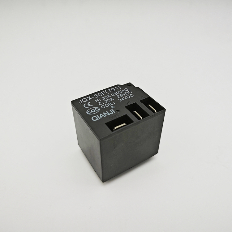
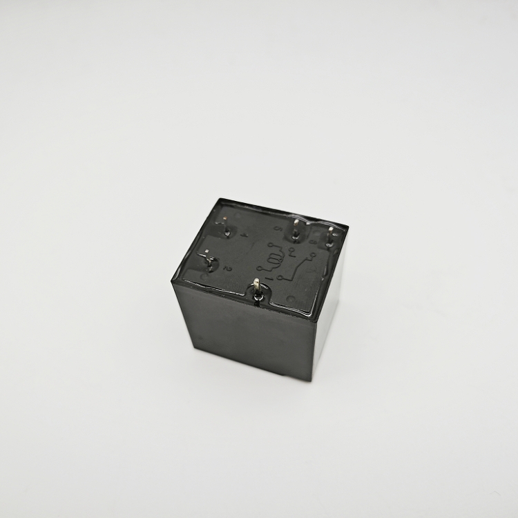
We sell this T91 5-pin relay, which is suitable for various industrial environments. It has a rated voltage of 12V, 24V, and can also be customized for customers. If you have any needs, please contact us
Coil wiring
85 pin: usually marked as the positive input point of the control circuit. Connect the positive wire of the control circuit to this pin.
Pin 86: The negative terminal of the control circuit. Connect the negative wire of the control circuit to this pin. Ensure the correct connection of these two wires so that the coil can generate the required magnetic field when powered on.
Contact wiring
30 pin: The common terminal, whether it is a normally open or normally closed contact, is connected to this pin. Connect the positive wire of the controlled circuit to this pin.
87 pin: One end of the normally open contact. When the coil is energized and the armature is attracted, this contact will close with pin 30, causing the controlled circuit to conduct. Therefore, connect the negative terminal of the controlled circuit or one end of the load that needs to be controlled to this pin.
87a pin (if present): One end of the normally closed contact. In some designs, when the coil is not powered, this contact closes with pin 30; After the coil is powered on, it will disconnect. Choose whether to use this contact according to actual needs and connect the circuit accordingly.
matters needing attention
Voltage and current matching: Ensure that the rated voltage and current of the relay meet the actual needs of the control circuit and the controlled circuit to avoid overload damage.
Wiring correctness: Carefully check whether the wiring is accurate and avoid problems caused by polarity reversal or poor contact.
Stability and safety: Ensure that all wiring is secure and reliable, avoiding the risk of poor contact or short circuit caused by vibration or looseness. At the same time, follow relevant safety regulations to ensure personal safety during the operation process.
We sell various types of relays. If you have any needs, you can contact us or check out our relay types
Search Term:5 pin relay wiring diagram,12v relay wiring 5 pin,12v 30a relay 5 pin wiring diagram,12 volt 5 pin relay diagram
wiring diagram for 5 pin relay
Chinese manufacturing and wholesale of 120A12V JQX-62F high-power relays